 Tom Santilli
.
June 07, 2024
.
EV Builders Guide
Tom Santilli
.
June 07, 2024
.
EV Builders Guide
In the world of electric vehicles, the term “Loss of Isolation” (LOI) sparks curiosity and concern. As EV conversions become more common, understanding how to maintain the electrical separation between the high-voltage (HV) system and the vehicle chassis becomes paramount. Federal regulations mandate the vigilance of Original Equipment Manufacturers (OEMs) in monitoring chassis for HV leakage, making LOI a prevalent concern and one of the more common failure modes in EVs. When building an electric vehicle, it is important to understand this principle as well as how to perform manual testing methods that ensure the HV system’s integrity.
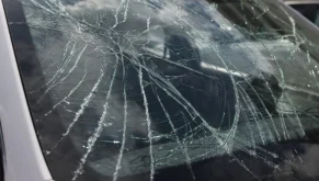
The high voltage system of an EV is an isolated “floating system”, meaning that there is no direct electrical connection between any of the high voltage and low voltage circuitry that is grounded to the vehicle chassis. To keep the high voltage circuitry isolated, all HV wires and components have insulating materials that create a high level of electrical resistance, protecting the chassis from high voltage exposure. Different stresses, however, can weaken the insulation and cause high voltage to find its way onto the chassis:
According to Federal Motor Vehicle Safety Standard (FMVSS) 305, the minimum isolation resistance barrier that must be maintained between the HV system and vehicle chassis is 500 ohms per volt (500 ohms/1 volt). Using a 300V system as an example, we can use use this safety standard to mathematically determine the minimum threshold of resistance:
In theory, if the resistance barrier were to decrease to a level less than 150k ohms, a “loss of isolation” diagnostic trouble code would be triggered.
In practice, OEMS will calibrate the software to flag isolation faults at a much higher resistance barrier level to ensure that the chassis electrical current never reaches a dangerous level.
If there must be a floating resistance barrier between the HV system and the chassis, then how much current is permissible? Ohm’s Law helps us understand why 500 ohms per 1 volt is used as a safety standard.
Ohm’s Law: V = IR
Electric potential (volts) = Current flow (amps) x resistance (ohms)
According to the National Electric Code, the upper safe limit for human exposure to electrical current is 5 milliamps. Although currents that are less than or equal to 5mA will provide some noticeable feel and discomfort, it’s not fatal. Considering the 300V system from before, lets rearrange Ohm’s law to calculate the amount of current that would theoretically flow into the chassis given a resistance of 150,000 ohms:
Solving for current: I = V/R
I = 3 00 volts = 0 .002 amps, or 2 mA
1 50,000 ohms
Under normal operating conditions, the maximum leakage current that could flow through between HV system and chassis is 2 milliamps, below levels that can cause bodily harm. Typically, the level of insulation resistance between HV components is much higher than hundreds of thousands of ohms, making the leakage current even smaller.
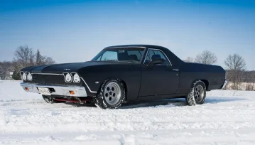
As more converted EVs hit the road with each passing year, it is critical that builders are aware of the risks associated with building a high voltage powertrain.
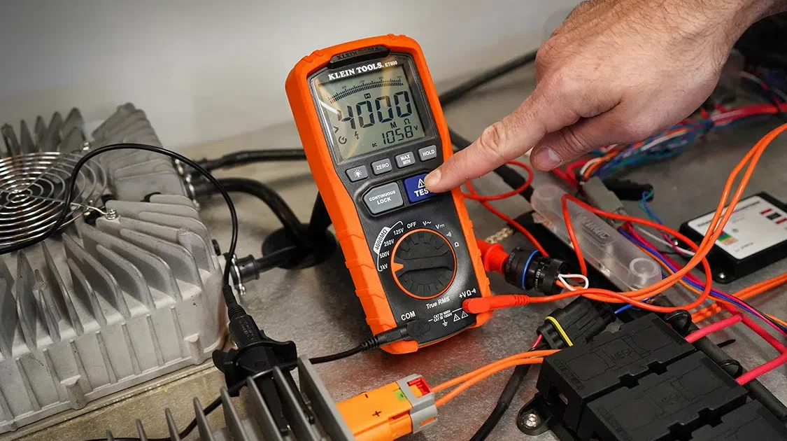
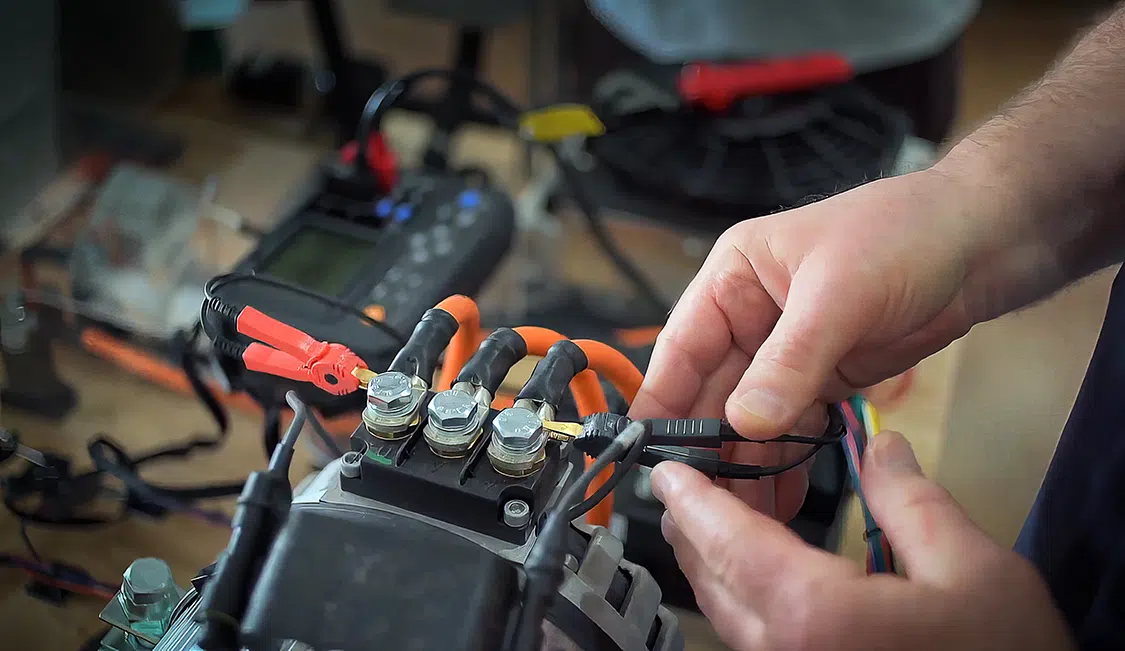
Megohmmeters, like the Klein ET600 Megohmmeter, perform a “stress test” to measure the resistance of the insulation by transmitting a high voltage, low current pulse through the material to measure resistance. Typical multimeters cannot transmit a high voltage pulse like megohmmeters can, and so are not able to accurately show whether or not a cable or component is completely insulated. If the resistance of the insulation is high, the megohmmeter will point towards the infinity (in the case of the Klein megohmmeter, 4000 Megaohms, 4,000,000,000 Ω, or 4 billion ohms), and if it is low, then the pointer indicates zero resistance.
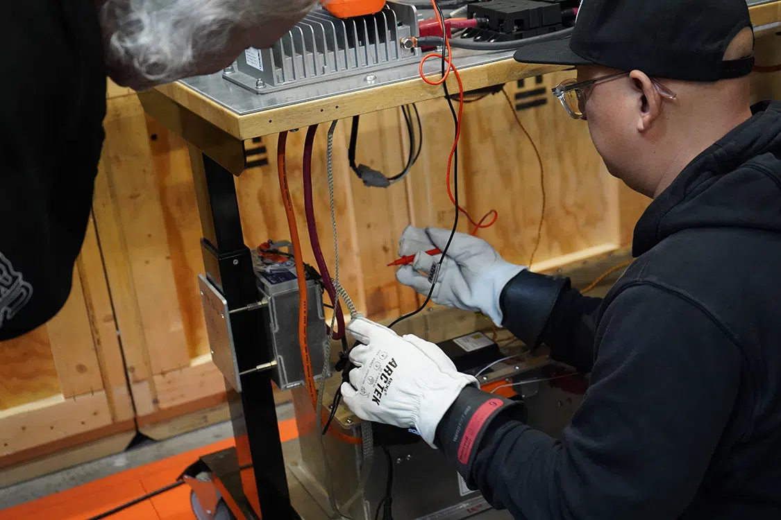
Jimmy Underhill of EV Swap Conversions using a megohmmeter to verify insulation resistance between AC of the J-1772 plug and the HV output of the AEM combined charge unit housing. Safety test documentation from AEM states the insulation resistance between these two points should be greater than or equal to 10 megohms.
Conductive Pathway:
Loss of Isolation
No Conductive Pathway:
Insulation Works
A reading that points to 0Ω indicates that there is a conductive pathway between the two points tested. If this result appeared while testing the insulation of high voltage cable, that would indicate a loss of isolation.
Since 4000M Ω is as high a resistance that the meter can measure, a reading of >4000M Ω indicates that that the insulation is working properly, and there is not a conductive pathway.
Any part of the high voltage system is susceptible to high voltage leakage, this includes:
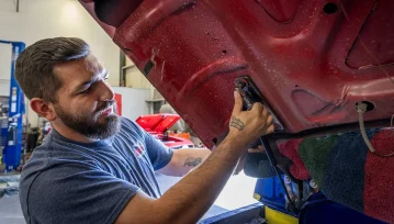
Whether you are installing new HV components or reinstalling one that was repaired, insulation tests are a critical quality assurance procedure to ensure that components will safely handle high voltage when under normal operating conditions. Manufacturers of high voltage components typically will provide safety testing documentation that demonstrates their level of insulation resistance between the high voltage connections of the component and its housing. Let’s take a closer look at what an insulation resistance test would look like for an HV component ready to be installed:
ELCON 1 KW DC/DC Converter TDC-IY Series:
Safety Test Data: Insulation resistance [HV] input to housing ≥ 20MΩ, test voltage is 1000VDC
At a 1000V test voltage, the megohmmeter reported a reading of >4000MΩ when testing HV+ input to housing and HV- input to housing, well beyond the minimum level of resistance outlined by the manufacturer. This means that the HV circuit is properly isolated from the housing and ready to be installed into a vehicle.
As more converted EVs hit the road with each passing year, it is critical that builders are aware of the risks associated with building a high voltage powertrain. By understanding loss of isolation and how to test for it in HV components, you can feel confident that your build is not only fast and slick, but safe as well.

Petit Jean Bronco Bash 2025
Morrilton, Arkansas
Goodguys 41st All American Get-Together
Alameda County Fairgrounds 4501 Pleasanton Avenue, Pleasanton, CA 94566
Southern Tradition Car/Truck Show
Canton, Ga.
Goodguys 24th Meguiar’s Del Mar Nationals Presented By FiTech Fuel Injection
Del Mar Fairgrounds 2260 Jimmy Durante Blvd., Del Mar, CA 92014
DCHS Car Show
Grand Prairie, Texas
We use cookies to enhance your browsing experience, serve personalized ads or content, and analyze our traffic. By clicking "Accept All", you consent to our use of cookies. Visit our Cookie Policy for more info.
Notifications


 Please wait...
Share Link